Case 5.3: ONRT Waves, trajectories
Case 5.3: ONRT in waves
1. Description of case 5.3
- Free running at model self propulsion point in calm water (mandatory)
- With propellers and rudders
- With bilge keels
- LPP = 3.147 [m], (model scale 1:48.935)
- Radius of gyration for yaw and pitch 0.246LPP (in air)
- Radius of gyration for roll 0.39B (in air)
- GM=2.068 [m] in full-scale (0.0423 [m] in model)
- Approach speed U0 = 15.1 [kn] in full-scale (1.11 [m/s] in model)
- Re∗=3.39×10⁶, Fr∗=0.20, g = 9.80665 [m/s2]
- Rudder rate 5.0 [deg/s] in full-scale (35.0 [deg/s] in model)
- Water depth: Infinity
- Regular waves
- Wave height (from top to trough) 63 mm on model scale, 3.08 m on full scale.
- Wave length to ship length ratio = 1.0, meaning that the wave frequency is 4.42 rad/s on model scale (0.633 rad/s on full scale). Consequently, the wave period is 1.42 s on model scale (9.93 s on full scale)
- Wave direction: head waves with the ship approaching at t=0
- The rudder execute (t=0) is when a wave crest is passing midship.
Re∗: Nominal Reynolds number, the Reynolds number when ship runs in calm water with constant propeller rate of revolution.
Fr∗: Nominal Froude number, the Froude number when ship runs in calm water with constant propeller rate of revolution.
All quantities are non-dimensionalized by desired approach speed (U
0), length between perpendiculars (L
PP):
(1)
where g is the gravitational acceleration and ν is the kinematic viscosity.
2. Experimental data
The submissions in case 5.3 will be compared to model tests carried out by IIHR. Roll decay result will be provided: time series of roll angle versus time.
3. Requested computations
The requested info are 3 submissions. You have to do 5.2.3 before to submit 5.3
Table 1: Requested computations
|
Manoeuvre |
Starting speed |
| 5.3 |
35° turning circle test, starting to portside |
Fr = 0.20 (equivalent to 15.1 knots full scale) |
- All calculations are to be conducted for model scale conditions.
- All simulations results should be provided in the format described in section 4.
- The propeller rate of revolution should correspond to the self-propulsion point of the model. When the RPM is unknown (because for example a constant thrust or actuator disk model is used in CFD based simulations) please indicate this.
- Similar to the experiment, the rudders should be controlled by Equation (2) during approaching before starting rudder execution for starboard side zigzag.
- During the turning circle manoeuvre, the rudders should go to the real geometric 35 degrees (not 35 degrees away from the neutral angle).
Please see section 4 for an example of the submission.
4. Format
- The trajectory
 and time histories of heave
  ¸ angular motions
  , dimensional velocities for 6DOF motions (u,v,w,p,q,r), rudder angle δ, and propeller rate of revolution n [rps] after the ship was released (t = t0), should be submitted.
- The ship position or trajectory should be given in an Earth-fixed coordinate system with X pointing North, Y pointing East, and Z pointing downward as shown in Figure 1. This XY axis system remains horizontal in the earth. The ship was released at (X0, Y0) when t = t0 . The roll angle (ϕ) is positive for pushing starboard into the water, pitch (θ) is positive for bow up position and yaw angle (ψ) is positive for bow turned to starboard. The reported trajectory is dimensional and angular motions should be reported in degrees. The angular velocities should be reported in degree second. The reported yaw angle should be the deviation of yaw angle respect to the target yaw i.e. ψ-ψC.
- All velocities for 6DOF motions (u, v, w, p, q, r) should be reported in ship-fixed coordinate system with x axis positive toward bow, y axis positive toward starboard and z axis positive downward. This xyz axis system rotates with the ship in yaw but not pitch and roll, i.e., remains horizontal in the earth. It is a so-called “yawed-only reference system”. Given this convention, the reported velocities are:
 (3)
(3)
 (4)
(4)
In Equation (4), the unit of  ,
,  and
and  is [deg/s].
- Rudder angle (δ) is positive when trailing edge moves to portside.
- All motions should be reported at O. The origin is located on O which is located at midships, the intersection of ordinate 10 the centre line plane and the still water waterline.
Time series of the manoeuvres should be send to the organizers in an excel file. The data shall be give on model scale, and it will be compared to model scale data.
The submission consists of an excel file (example is given) with 19 columns and with rows for every time step. The time step is free to chose, but a small enough time step somewhere around 0.05 to 0.01 is recommended to get sufficient accuracy. The following quantities are asked:
Table 2: Submission variables
| Symbol |
Item |
Unit |
| t |
time |
s |
| x |
X position in earth fixed system |
m |
| y |
Y position in earth fixed system |
m |
| z |
Z position in earth fixed system |
m |
| ϕ |
Roll angle |
degrees |
| θ |
Pitch angle |
degrees |
| ψ |
Yaw angle |
degree |
| u |
surge velocity |
m/s |
| v |
sway velocity |
m/s |
| w |
heave velocity |
m/s |
| p |
roll rate |
deg/s |
| q |
pitch rate |
deg/s |
| r |
yaw rate |
deg/s |
| δ |
Rudder angle |
deg |
| n |
Propeller revolutions of portside propeller |
rpm |
These data are illustrated in Figure 1. The origin is located on O. The time t=0 is the time when the steering starts. The initial direction of the model is the direction of X-axis. Initial conditions at t = 0 are: X
0=0, Y
0=0, u=U
0, δ=δ
0 (which is the neutral rudder angle)
There is a right-handed earth-fixed coordinate system x
0y
0z
0, and a right handed body-fixed coordinate system xyz. The body-fixed coordinate system has its origin in O (midship), and the xy plane heels and pitches. The heading angle is defined as the angle between x- and x
0-axis. u and v are the velocity components in ship direction. the hull drift angle will be defined as β=atan(-v/u), and the total velocity U=√(u
2+v
2).
 Figure 1: Illustration of the sign convention of the earth-fixed and body-fixed coordinate system.
Link to an excel file, which a submitter can download.
Figure 1: Illustration of the sign convention of the earth-fixed and body-fixed coordinate system.
Link to an excel file, which a submitter can download.
7. Elaborated example for case 5. 3: 35° turning circle manoeuvre to portside
For case 5.3, the time traces and a bird-eye view will be plotted for comparison as Figure 2. Time traces will be displayed in Figure 3. From these time traces, the typical characteristics will be determined. These characteristics will be the comparison variables. Table 3 gives these characteristics. The bold variables are the primary validation variable, the non-bold are the secondary validation variables.
 Figure 2: Example trajectory (bird-eye view) of Case 5.3,
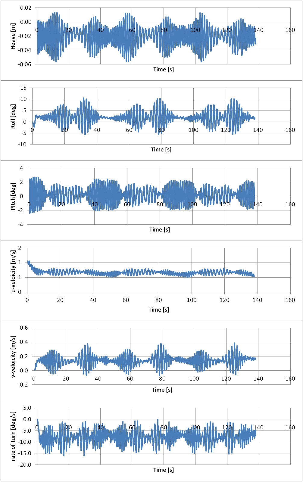 Figure 3: Time traces of important signals for Case 5. 3; experimental values
Data reduction will take place to derive the quantities HD and μD:
For the time trace under consideration, these values are determined. To determine HD and μD and , the position difference between ψ=630° and ψ=990° is used..
Table 3: Comparison values and EFD values for the 35° turning circle manoeuvre
| Category |
Unit |
Validation Variables |
EFD |
|
[-] |
Drift distance / LPP (HD/LPP) |
0.386 |
|
[deg] |
Drift direction (muD) |
112 |